Application of Gear Flowmeter in Hydraulic System of Machine Tools
Keywords: gear flow meter machine hydraulic system position monitoring machine tool hydraulic system as an auxiliary power source, is an integral part of the machine tool, such as spindle loose knives, gravity balance, clamping and release of the functional components, tool magazine drive, etc. Open hydraulic drive. In order to ensure the reliable operation of the machine tool, each time an action command is executed, a reliable completion signal must be detected after the action is completed to perform the next action so as to prevent the malfunction signal from causing the machine tool to malfunction and cause a safety accident. Therefore, it is very important for the hydraulic system of the machine tool to detect the arrival signal of the component.
Flowmeter as a detection element is widely used in coal and petrochemical industries. As a flow detection control element, high-precision flowmeter has a certain application in the aerospace hydraulic servo control system, but it is less applied in the conventional machine tool hydraulic system. The number of pulses issued by the flowmeter can truly reflect the principle of the stroke of the cylinder. The gear flowmeter is applied to the hydraulic system of the machine tool, which solves the shortcomings of the previous system design and has achieved good results.
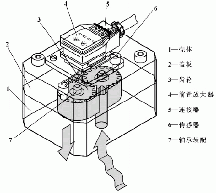
1 Introduction to Gear Flowmeters There are many kinds of flowmeters, their functional principles are different, and their application fields are also different. The gear flow meter is based on the principle of a gear motor. The two spur gears are driven by the liquid flow in the measuring chamber without contact; the motion of the gears is detected by two non-contact sensors located in the cover plate, between the sensor chamber and the metering ring chamber. , With a non-magnetic anti-pressure diaphragm; When the measuring mechanism rotates a tooth, the sensor sends out a pulse signal, corresponding to a tooth's oil ΔV through the flow meter, through the preamplifier, the signal is converted into a square wave signal; two channels Detection can have higher resolution and confirm traffic direction.
The gear flow meter has high precision, good viscosity and temperature characteristics, high working pressure and relatively low price, and is suitable for application in the hydraulic system of the machine tool. Its structure is shown in Figure 1.


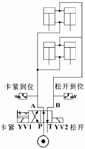
In the research and development of a national high-speed Gantry five-axis machining center, a certain company was involved in the double swing head exchange by four self-locking studs to achieve a double swing head loose card. In order to solve the above problem, a flow meter is provided in the hydraulic loose card loop as a snap-release in-position detection element. The flow meter can truly detect whether the cylinder clamping and releasing is in place by detecting the amount of oil passing through. Because the flow meter is installed on the loop, it is not limited by the size of the mechanical structure, and successfully solves the problem of the double pendulum head loose card in place detection. The schematic diagram is shown in Figure 3.

Set the required oil volume for each pull screw to clamp V0 = 10mL, and the total oil required for the clamp action is 4V0 = 40mL. The author selected the German KRACHT company VC0.2 model gear flowmeter, and the gear geometric volume ΔV=0.245mL, ie Every time a pulse signal gear flowmeter passes 0.245mL oil, the number of pulses needed to complete the clamping action is:

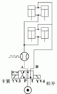
In order to solve the above problems, the company adopted the method of configuring the gear flow meter on the hydraulic circuit of the high-speed vertical machining center tray exchanger to increase the cylinder displacement measurement and set the corresponding speed switching point in the middle of the stroke of the cylinder to realize the pallet exchanger. Speed ​​control, schematic diagram shown in Figure 5.


Lset is to set the sending point location;
L0 is the total stroke of the cylinder;
D is the cylinder diameter;
ΔV is the flowmeter geometric volume.
3 Conclusion Based on the number of issued pulses can truly reflect the principle of the cylinder stroke, gear flow meter can be applied to the hydraulic system for position monitoring and detection. The gear flowmeter has the advantages of not occupying the mechanical design space, flexible position detection setpoint, and being less susceptible to environmental interference. It has a broad application prospect in the hydraulic system of the machine tool.
Variable valve timing (VVT) solenoid or oil control valve controls the oil flow according to the engine speed and load. VVT solenoid is a vital part of the variable valve timing system.
The Oil Control Valve (OCV) is a a critical part used in every engine that is fitted with variable valve technology (VVT). A single control valve will regulate the supply of oil to a designated VVT hub, to advance or retard the timing by altering the camshaft angle position. Controlled by the ECU, the OCV receives electrical signals, instructing it to adjust the oil flow as required, in accordance to current driving conditions.
Bmw Variable Valve Timing,Bmw Vvt Solenoid,Intake Timing Solenoid,Camshaft Variable Timing Solenoid
Wenzhou Zhongking Parts Co.,ltd , https://www.oemvvt.com